Purpose
Non-melanoma skin cancer (NMSC) typically develops within the outermost layer of the skin, i.e., epidermis. Basal cell carcinoma (BCC) and squamous cell carcinoma (SCC) are the two major types of NMSC [1]. NMSC is the most common malignant skin cancer that has increased in frequency in recent years, and BCC and SCC are the most frequent types. In the United States, about 5.6 million people are diagnosed with squamous cell carcinoma or basal cell carcinoma each year (some patients have more than one type of NMSC), with BCC accounting for 80% of cases [2, 3]. The treatment of NMSC includes surgery, curettage, cryotherapy, micrographically oriented histographic surgery (MOHS), and radiotherapy [4].
High-dose-rate (HDR) brachytherapy (BT) is an efficient choice of radiotherapy, particularly when 1) Surgical removal of tumorous cells may damage the appearance, the patient is old, or the surgery can have side effects (BT as non-invasive technique can provide an ambulatory treatment with high compatibility) [2, 5]; 2) Lesions are shallow, covering extensive areas, where organs vulnerable to radiation are situated right below the lesions (e.g., scalp and hand skin); and 3) If there is a high-risk of recurrence and positive surgical margin (in this case, HDR brachytherapy is offered as an adjuvant treatment) [4, 6].
Skin brachytherapy can be performed using interstitial techniques, in which a subcutaneous catheter is surgically placed within or near the tumor. Furthermore, it can be performed using superficial techniques through molds/applicators. In superficial techniques, HDR sour-ces (> 12 ) offer rapid treatment. As a result, HDR brachytherapy with surface applicators is an efficient alternative to interstitial techniques administered through ambulatory surgery [7].
There are some commercially available surface applicators used in BT, including Leipzig and Valencia applicators, which are employed to treat lesions with a diameter smaller than 3 cm, and superficial moulds or flap-style applicators, such as Freiburg flap, catheter flap set, and HAM applicators, which are used to treat lesions situated in larger areas or in high surface curvature, e.g., the ears, nose, and head skin [8-12]. Commercially available flap-style applicators have catheters in fixed positions, and can be cut to fit the area to be treated. These applicators can also be placed on thermoplastic masks to ensure that the patient and applicator are in the same position, improving repeatability. Custom brachytherapy moulds are fabricated to fit the shape of lesion. Catheters must be fixed near the tumor surface, so that radioactive isotopes can pass through and the entire tumor volume can be covered.
Custom moulds are fabricated from flexible materials, such as acrylic resin, granular boluses, silicon, polyme-thyl acrylate (PMMA), soft tissue-equivalent materials, and wax (used in dentistry) [13]. In a study, head mould was fabricated using irreversible hydrocolloid molding materials and dental stone [1]. Similarly, Jumeau et al. designed three wax applicators, and used silicon eight times and Freiburg flap once. They showed that custom-made moulds in HDR brachytherapy may be very effective in treating skin lesions [7]. Guix et al. employed polyme- thyl methacrylate (PMMA) custom-made moulds as dental prostheses in 136 patients with BBC or SCC. They reported a local control rate of 98% in 5-year follow-up in all patients [14]. Additionally, Jaberi et al. analyzed the effects of a silicone elastomer custom-made mould in an institute [15].
The use of flap-style applicators to treat lesions in small areas with high surface curvature, such as the nose, is complicated due to the need for catheters placement in different directions and heights [11]. In such cases, using custom moulds made from dental stone or granular boluses is a more effective alternative. Dental paste has disadvantages, such as a complete mismatch between its attenuation coefficient and water, or soft tissue attenuation coefficient and its non-uniform final shape. Conversely, granular boluses pose a risk for damaging brachytherapy needles due to the adhesion of bolus material. Furthermore, the necessity to manufacture a custom mold for each patient is labor-intensive, and can significantly increase procedural time, particularly in busy clinical departments. The current study aimed to develop a new in-house low-cost surface mould applicator, and to evaluate its dosimetry for high-dose-rate (HDR) brachytherapy using cobalt-60 (60Co) radionuclide. Here, medical silicone and plexi-based templates were employed to fabricate the mould.
Particular radiation detectors are needed to experimentally determine the dose deposition and isodose curves to control the computational algorithm because of the high-dose gradient and rapid dose reduction near brachytherapy sources. Therefore, for this study, film dosimetry was chosen. Monte Carlo (MC) simulation method, due to its high capabilities in modelling particle transport, absence of practical dosimetry problems, and time limitations, can yield favorable results to improve the accuracy of dose calculation.
In summary, to validate the constructed BT mould for clinical use, its performance was examined using Gafchromic EBT3 film and Monte Carlo simulation.
Material and methods
Film measurements
Gafchromic EBT3 films (Ashland Inc., Covington, NJ) of 8 × 10 in2 size were used in the present study. The main characteristics of this type of film, as compared with EBT2 films, are the elimination of orientation dependence [16], and the accuracy of multi-channel dosimetric ability (RGB, red-green-blue) is greater than 1% at different scanning periods after irradiation [17]. Application of this film was performed according to the American Association of Physicists in Medicine Task Group (AAPM TG) 55 report [18].
Film calibration
Considering the characteristics of EBT3 films, which are independent of energy at photon energies above 100 keV [19], Varian linear accelerator with 6 MV photon energy was used to calibrate the film, and the film was cut into 2 × 2 cm2 pieces. A slab phantom with a thickness of 1 cm and dimensions of 16 × 18 cm2 was employed to irradiate the film. Two slab phantoms were placed on top of the films, and ten slab phantoms were positioned under the films to create buildup and eliminate backscattered radiation, respectively.
A field size of 10 × 10 cm2 was used. Source surface distance (SSD) referring to the distance between the radiation source and surface of the slab phantom was set at 100 cm. Moreover, to obtain the calibration curve, films were exposed to doses ranging from 0 to 600 cGy (i.e., 0, 100, 150, 200, 250, 300, 350, 400, 450, 500, 550, and 600 cGy).
Scanning protocol
All irradiated films were scanned after 48 hours with a Microtek ScanMaker 9800XL scanner. Values of the output pixels of the scanner’s red channel were extracted and employed via ImageJ software to analyze the images. This software was used to obtain the calibration curve and convert pixel value to dose. Films were scanned at a resolution of 150 dpi and 48 bits, and saved in uncompressed tagged image file format (TIFF). Region of interest (ROI) was considered at the center of the image, and delivered dose was proportional to the mean pixel value in that region.
Mould construction
The applicator comprised medical-grade silicone. Material concentration percentage was calibrated to allow flexibility of the mould. We tried to obtain a final material composition that did not have a high attenuation coefficient, and finally, we attained a flexible mould with an attenuation coefficient of 0.89.
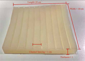
The applicator was composed of silicone materials with different thicknesses (i.e., 1.5 cm, 1 cm, and 0.5 cm) in dimensions of 10 × 10 cm2 with nine catheters, which were internally embedded parallel at a distance of 1 cm from each other (Figure 1). It can be mounted onto a mask or other immobilization device to create a repeatable geometry for source positioning.
Experimental setup
In this study, a SagiNova® HDR afterloader (version 1.2.4; Eckert & Ziegler BEBIG GmbH, Germany) with a 60Co source (model Co0.A86) was employed. Dosimetric parameters of this source were validated by members of the team, and validation details regarding 60Co source (model Co0.A86) were derived from a study [20].
Slab phantoms have tissue-equivalent density. One 0.5 cm slab was placed where the tumor’s depth was assumed, and then 10 additional 1 cm slabs under the mold were positioned.
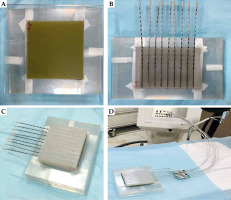
Two 10 × 10 cm2 pieces of film were used for 2D dose measurement, one placed directly under the mould and the other 0.5 cm below it. Another mould with a 1.5 cm thickness was placed over the measurement setup to provide full scattering conditions. Finally, nine steel needles with a length of 21 cm were used in mould grooves. The details of the procedure are shown in Figure 2. This geometrical setup was fully considered in the simulation and planning steps.
Fig. 2
A) Two 10 × 10 cm2 Gafchromic films placed over and under the slab phantom. B) Mould with the needle attached. C) Mould was placed over the setup to provide full-scattering conditions. D) Final setup to achieve the measurements with mould brachytherapy, phantom, and SagiNova® cobalt-60 HDR afterloader
MC simulations
MCNPX calculation code uses computational methods to transport ionizing radiations, such as electrons, neutrons, and photons, in which dose distribution is determined with a simulation of particles being transported through respective geometry. In the current study, the MCNPX code version 2.6 was applied for Monte Carlo simulation. As shown in Figure 3, the simulation geometry using MCNPX code was conducted according to the geometry setup. Visual Editor version X22S package was used to observe the simulation geometry and accuracy. Isodose curve was illustrated with OriginPro® version 2022 software (OriginLab Co., Northampton, MA, USA).
Fig. 3
A) A 2D view of the simulated geometry measurement setup, with thicknesses of 0.5 cm, 1 cm, and 1.5 cm. B) Top view of the mould, while a single source is placed inside the needle. C) A view of simulated BEBIG cobalt-60 source model Co0.A86 (all dimensions in mm, but not to scale)
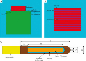
Mesh tally is a valuable mechanism for visualizing the results and comparing energy. A mesh tally was employed to calculate the dose at different points, and to obtain the isodose curves in a configuration for three different mould thicknesses.
PEDEP option used a rmesh card that showed the average energy deposition per unit cell volume,
CT setup
A 64-slice CT scanner (Siemens Somatom) with a brachytherapy protocol and slice thickness of 1 mm was utilized for tomographic imaging to examine brachytherapy needles with high accuracy at the treatment planning, which was sent to treatment planning system.
Flexibility of applicator to phantom’s surface
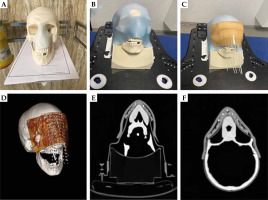
This step was performed to investigate the flexibility of the mould to the curve body surface. According to Figure 4A-D, a tumoral tissue was assumed for the nose of skull moulage (i.e., a light blue structure in Figure 4A represents pseudo target). First, a 3-point thermoplastic mask of a skull was employed to fix the skull, and a 10 × 10 cm2 mould with 10 inserted needles in its grooves was placed on top of the pseudo target. Then, a sticker bolus was placed on the setup to ensure the mould and needle positional reproducibility during subsequent steps. Finally, a CT scan with a thickness of 1 mm was taken from the final setup.
Data comparison
The results were compared in two ways; the following is a summary of the details.
Comparison of control points defined based on the geometric model
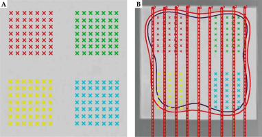
In this study, to create treatment plans, SagiPlan® version 2.0 treatment planning system was utilized. Accordingly, two slices were determined in the treatment planning system for each mould, one under the mould and the other at a distance of 0.5 cm. For each slice, there were four control groups, each with 49 points (Figure 5). Paired sample t-test was used to compare data of all points in each slice derived from the simulation, treatment planning system (TPS), and film dosimetry. An error level of less than 0.05 was assumed to be significant. Data were analyzed with SPSS version 26 (IBM Corporation, Armonk, NY, USA). Furthermore, by finding a difference between TPS, MCNP, and film data for each pair, their average and standard deviations were calculated using SPSS version 26 software.
Results
Calibration curves
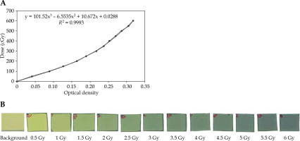
Optical density (OD) values were calculated with the irradiated dose. In addition, the measurement of the mean percentage error of OD values was repeated twice. After obtaining values for the net OD, the film calibration curve was extracted as the absorbed dose based on the net OD. It was then drawn into ImageJ (Figure 6).
Comparison of control points defined based on geometric model
Table 1 demonstrates the parameter p-value extracted from comparing TPS and MCNP data, and TPS and film data using three mold applicator thicknesses. The difference in the dose level measured by TPS and film dosimetry was higher on the mould contact plane (depth, 0 cm) than on the plane located 0.5 cm away from the applicator (depth, 0.5 cm). These differences were statistically significant. However, no significant difference was observed when increasing the distance to a depth of 0.5 cm for both moulds with thicknesses of 1 cm and 1.5 cm.
Table 1
Data comparison between TPS, MCNP, and film across different mould thicknesses at considered control points
No significant differences were obtained comparing the simulation and TPS output for mould thicknesses of 1 cm and 1.5 cm at all measurement depths, as demonstrated in Table 1. For a mould with a 0.5 cm thickness, the dose values measured by TPS were higher than the dose values measured by MCNP, and the difference was statistically significant. Moreover, the film dosimetry and Monte Carlo simulation were performed, and the results obtained were compared with the dose distribution calculated by TPS. Good consistency was observed between the calculation results from the TPS and film dosimetry at the prescribed depth of 0.5 cm, with mean differences of 0.70%, 0.40%, and 0.19% for mould thicknesses of 0.5 cm, 1.0 cm, and 1.5 cm, respectively. However, higher discrepancies were found at the phantom surface with 1.00%, 0.80%, and 0.56% dose differences for the considered mould thicknesses, respectively. Also, mean differences between the results obtained from the MC simulations and TPS output at the prescribed depth of 0.5 cm were 0.73%, 0.60%, and 0.08% for mold thicknesses of 0.5 cm, 1 cm, and 1.5 cm, respectively, which were in close agreement. On the other hand, higher variations were found between the TPS and MC at the phantom surface, with dose differences of 1.30%, 0.70%, and 0.13% for the considered mould thicknesses, respectively.
Comparison of two-dimensional isodose curves
Figure 7 presents a comparison of two-dimensional isodose lines obtained from MCNP dose calculations (represented by dashed lines), film measurements (solid lines), and TPS calculations (dotted lines) for three different mould thicknesses at depths of 0 cm and 0.5 cm. Furthermore, numbers on the isodose lines are represented in percentage units in Figure 7.
Fig. 7
Comparing two-dimensional isodose lines obtained from MCNP dose calculations (dashed lines), film measurement (solid lines), and treatment planning system (dotted lines) for three mould thicknesses at depths of 0 cm and 0.5 cm. All axis dimensions are in centimeters
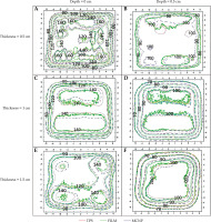
Quantitative evaluation of isodose lines distributions for all three moulds on a plane that was in contact with it (i.e., depth, 0 cm) and at a depth of 0.5 cm in the PMMA phantom, presented an approximate distance difference of 0.1 cm to 0.6 cm between the isodose lines of 60% to 90%, respectively. Increasing the dose gradient from 60% to 90% isodose and any uncertainties during the practical and simulation steps would result in a higher dose difference between the three data sets and their resulting isodose lines.
The isodose curve in Figure 7F shows that the dose distributions obtained from the EBT3 film and MC simulation are closely consistent with the dose distribution obtained from the SagiPlan®.
Discussion
Special NMSC applicators, such as Valencia, Leipzig, and Freiburg flap, can be utilized for HDR brachytherapy. These applicators’ geometry makes it difficult to treat lesions in regions with significant surface curvature. Previous studies have demonstrated that the mould technique offers effective local control and good aesthetics [1, 5, 21].
In HDR surface brachytherapy, a common technique involves utilization of pre-designed or custom-made applicators [15, 22-27]. Diefenhardt et al. reported the clinical response and follow-up outcomes of six patients with perinasal/periorbital skin cancer treated with high-dose-rate brachytherapy mould. After a median follow-up period of 335 days, all patients demonstrated a complete clinical response. Additionally, the target coverage was adequate, with a median of 98.9% within 90 days [28].
In this study, a mould applicator specific to NMSC treatment in HDR brachytherapy was created, and applicator’s dosimetry was examined. Our mould brachytherapy applicator is made of elastic silicone material. The location of catheters is pre-drilled, and a set of catheters is placed at a distance of 1 cm from each other. This applicator can also treat large and curved surface lesions. It can be mounted on the mask to create a more repeatable geometry. In addition, it is a low-cost facility that can be customized for each lesion depth and dimension.
Dose calculation accuracy is important for the therapeutic method and treatment efficiency. As the gold standard for dose distribution and comparison of other dose calculation methods and algorithms, Monte Carlo is considered the most accurate method for calculating doses.
For HDR skin brachytherapy, Granero et al. examined the limitations of TG-43 dose calculation formalism using a surface mould, along with catheters. For validation, Geant4 MC code was employed. The results from 60Co source showed the highest difference (9%) in the first millimeter of the skin surface. However, at a distance of 0.4 cm from the skin’s surface, this difference was zero [12]. In another study, Amoush et al. examined a catheter-based HDR brachytherapy applicator, and compared data from film and MC measurements using TG-43 dose calculations. The results suggested that the highest difference between TPS and MCNPX data was 0.05 cm from the surface [29]. P-values in Table 1 show that our findings are consistent with the previously reported studies. However, a significant difference was observed between the measured, simulated, and TPS reported dose at 0 cm depth (i.e., the surface of the phantom in contact with the mould), which can occur due to uncertainties in the control point in TPS and film in this high gradient region. There were no significant differences between the TPS results obtained for 1 cm and 1.5 cm applicators compared with the simulation output. Increasing the mould thickness improves the compatibility of the data with TPS. Vijande et al. also investigated the flap applicator dosimetry. The highest difference in dose distribution between MC and TG-43 was 5%. Moreover, the difference in dose distribution at the prescribed depth, typically situated 0.5 cm away from the surface, was reduced comparing with dose distribution on the skin surface [30].
Data comparison in Figure 7 shows that the differences between the isodose lines obtained from the TPS and MCNP decreased for the planes located at a depth of 0.5 cm when compared with the surface contact with the applicator. Also, this figure shows that by increasing the thickness, the consistency maximized between TG-43-based TPS and MC regarding the isodose lines. These differences are because the TG-43-based TPS systematically assumes full scattering conditions and overestimates the actual delivered dose [31]. However, it is a fundamental problem in surface brachytherapy that is not usually met in clinical practice, resulting in approximately 5% of local dose errors, especially in the first 0.5 cm depth of the skin. As a result, the TPS results in each plan were higher than the MCNP simulation output, and the film reading at a distance of less than 0.5 cm from the phantom surface was reasonable.
EBT3 film has near tissue-equivalent and easy compatibility through cropping, and by using it, the dose distribution inside the plane can be measured during a single exposure. According to Chiu-Tsao et al. study, these films are energy-independent in photon energy higher than 0.1 MeV [32, 33]. Therefore, EBT3 films can be used as a dosimeter for 60Co sources with an average photon energy of 1.25 MeV. To avoid uncertainty in dose calculations associated with TG-43, the films were calibrated under orthovoltage beam quality instead of calibrating films under 60Co HDR. Different studies reported that the difference between TG-43 and measured doses should be locally analyzed [31, 34]. Uncertainty in film dosimetry is caused by two factors: the dose level, and the difference in the pre- defined distance between the source and film in TPS and film dosimetry at experimental site. The measurement with EBT3 film by Aldelaijan et al. reported a 3% uncertainty in doses < 2 Gy. However, when a high-dose is prescribed at a greater depth (e.g., 6 Gy at a depth of 1 cm), the uncertainty in dose determination is reduced [31]. On the other hand, Jaberi et al. reported a difference of approximately 35% caused by positional uncertainty in dose calculations between TPS and film dosimetry on the surface. Uncertainty is depth-dependent, and correlate with it inversely [15]. The results from the film dosimetry at the distance of 0.5 cm were close to these proposed by the TPS.
As expected, a statistically significant difference was observed between the dose reading from the film dosimetry and the dose calculated on the surface that was in contact with the mould (p-valuedepth = 0 cm, height = 0.5 cm) = 0.024, p-valuedepth = 0 cm, height = 1 cm = 0.042, p-valuedepth = 0 cm, height = 1.5 cm = 0.048), which was due to high-dose gradient at this bolus level. Jaberi et al. demonstrated that the results of readings from the film on the surface of phantom were invalid [15].
A commonly studied technology in recent years is 3D printing, which produces a customized bolus for skin cancer treatment. Park et al. developed a 3D-printed elastic skin applicator individually for surface brachytherapy. Freiburg flap and rigid applicators were also used to compare dosimetry results. EBT3 films were irradiated in the axial plane inside the head phantom for each applicator. The results of elastic applicator were in good agreement with the calculations. It showed the highest gamma passing rates and the lowest SD among Freiburg flap and rigid applicators. According to CT images, the elastic applicator demonstrated better adjustability to irregular and curved surfaces than the rigid applicator [35].
In the current study, a flexibility test was applied to the mould after one year, showing no deformation and flexibility change in the applicator. According to Figure 4, air gap between the mould and the target patient’ surface is acceptable, as this mould has good flexibility and fits well on the target patient’s surface. Since a large dose difference can be seen in HDR brachytherapy with differences lower than 0.1 cm, utilization of a flexible applicator is useful for surface skin HDR brachytherapy.
The most common barriers in 3D-printed applicators are long printing time (because the filling percentage is reduced to improve the geometrical accuracy of prints; hence, the printing time increases) [36], limited print volume (this is because the minimum printing time is 12 hours by most commercial printers), high implementation costs (printer, materials, physical space, and personnel education), biocompatibility of materials [37], and printer size limitation [38], while our mould applicator is reusable for several patients and cost-benefit. In addition, using a thermoplastic mask for each patient can increase its intra- and inter-fractional positioning accuracy.
In the current study, the dosimetry of the surface mould applicator was performed through simulation and experimentally. This flexible applicator fits well into irregular and curved surfaces of the body, and can be mounted on thermoplastic masks to reduce uncertainty of the treatment setup, leading to better adjustment by reducing unwanted air gaps, and causing better distribution between planned and delivered doses. Moreover, this applicator can be trimmed to the desired size to achieve a better formation around the lesion.
Conclusions
The new low-cost surface mould was developed, and dosimetry verification showed its water-equivalence at 60Co photon energies, consistent with TPS calculations at the depth of treatment. Its effectiveness in NMSC lesion therapy is highlighted, along with potential clinical recommendations. However, because of the mould attenuation, the TG-43-based TPS overestimated the dose delivered through it, especially at the pseudo-skin surface, which emphasizes the necessity for a model-based TPS algorithm.


